Pt100 4 Wire Connection Diagram
Wiring For Rtd Configurations
2 3 And 4 Wire Rtds What Is The Difference

4 Wire Pt100 And 2 Wire Pt1000 Elmb Temperature Adapter
How To Hook Up A 4 Wire Pt100 And How To Get Temperature From It
Technetea Temperature Measurement With A Pt100 Or Pt1000 Sensor

Kd 5974 Wire Rtd Cable 4 Circuit Diagrams Free Diagram
As the 4 wire connection method fully compensates for all lead resistance we strongly recommend that this is used when using a high specification of pt100 such as 1 5 or 1 10 din tolerance.
Pt100 4 wire connection diagram. The best configuration for a specific application depends on a number of factors however the sensor configuration must match with transmitter otherwise leadwire resistance cancellation circuitry may be ineffective. Each wire is maybe 1 ω of resistance. Flow pressure measurement industrial process control ads1248evm 20 28 pin tssop ads1247 48 24 bit complete temperature measurement adc. Idac generates the sensor excitation and.
The following connection diagrams illustrate how to connect various rtd types to your daq device. 2 wire rtd connections the 2 wire rtd configuration is the simplest among rtd circuit designs. Rtd pt100 3 wire wiring diagram gallery rtd sensors 2 3 4 wire rtd sensors resistance temperature detectors. It is in simple terms a resistance that changes with temperature.
A pt100 normally has 3 wires. 2 3 4 wire rdt pt100 to pt1000 temperature measurement. When connected to the amplifier the smart amp will measure the voltage across the rtd and also across the wire pairs. Difference between 2 wire rtd 3 wire rtd and 4 wire rtd s rtds resistance temperature detectors are offered with 2 3 or 4 lead configuration.
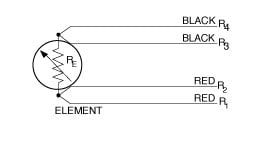
Where do those wires go pt100 1. A pt1000 measuring element in class a also offers good measurement accuracies in a 2 wire connection and represents an economical alternative to 3 or 4 wire connections for machine building. It is called a pt100 because at 0 deg c it will measure 100 ohms. What is an rtd rtd types uses and more by jms southeast.
For example here s the approximate resistances of a 4 wire pt100 rtd at 0 c for a pt1000 the middle resistance would be 1002 ω rather than 102 ω. 3 wire rtd connection advantage. There are three types of wire configurations 2 wire 3 wire and 4 wire that are commonly used in rtd sensing circuits. Sor resistance temperature detector rtd proflow systems.
3 wire rtd wiring diagram awesome rtd sensor temperature ppt video. We believe it is a false economy to specify a high tolerance temperature sensor with its associated cost and then use an inferior measuring system. Because a very small change in resistance happens with each degree in temperature the. At ambient it will be around 138 ohms.
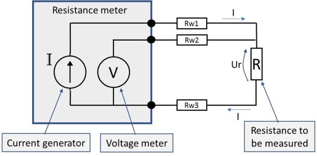
Resistance Measurement 2 3 Or 4 Wire Connection How Does It

Pt100 Sensor With Microcontroller Circuit Diagram
Positive Analog Feedback Compensates Pt10 Maxim Integrated

Pt100 Temperature Sensor Pinout Sensor Temperatures Electricity

Measuring Temperature From Pt100 Using Arduino Projetos Arduino

Measuring Temperature Using Pt100 And Arduino With Images

Measuring Temperature From Pt100 Using Arduino

Pin By Lisa Xi On Shenzhen Senster Electronics Co Ltd

Interpretar Un P Id Con Imagenes Ingenieria De Procesos

Precision Contract Manufacturing Stahl Metall Engineering Is

New Bmw E46 Head Unit Wiring Diagram Electrical Wiring Diagram

Electric Bike Controller Wiring Diagram In Addition Electric Motor

Rims Tube Controller Build With Images Home Brewing Beer Home
